Rectangular Duct Applications

(Full OPM)
1) Duct Connection
Option 1: Sheet Metal Screws
(2) #10 Sheet Metal Screws thru strut and duct walls at each corner
1" O.C. and 1" Max from edge, each corner, Typ
Use solid channel for horizontal members if using this option
Approved Sheet Metal Screws (#10 Size):
- ITW Buildex (ESR-1976 & ESR 3223)
- Simpson Strong-Tie (ESR-3006)
- Darts (ER-5202)
- Elco (ESR-3294)
- Hilti (ESR-2196)
Option 2: Weld
Only for Duct 18 ga. and thicker
Start from Duct edge, each corner, Typ
Flare-bevel field weld, both sides
2" long
2) Horizontal Beams
Maximum Allowable Uniform Vertical Load per Beam (lbs)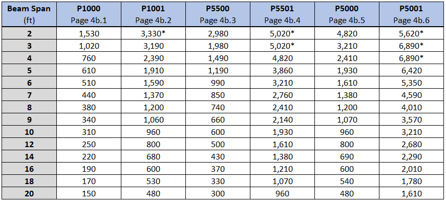
Notes:
1. Values in this table apply only to Unistrut brand products. Unistrut channels are stamped with the name "UNISTRUT".
2. Values in this table are valid with all solid, T, WT and HS pierced channels of the above channel profiles.
3. * Load is limited by spot weld shear. Weld shear and tension are accounted for in the above listed capacities.
4. Refer to OPM Page 4b.0 for the detailed calculation procedure.
3) Brace Member
Maximum Horizontal FP Force (lbs) [ASD] at 45° from Horizontal
Notes:
1. Values in this table apply only to Unistrut brand products. Unistrut channels are stamped with the name "UNISTRUT".
2. Values in this table are valid with all solid, T, WT and HS pierced channels of the above channel profiles.
3. These brace members are valid for angles from 0° to 60° from horizontal. Refer to product or OPM pages for capacities.
4) Brace Fitting
FP Load Capacity (lbs)
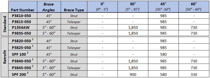
Notes:
- Use with P3860 base.
- Use with LS 100 base.
- Use with LS 200 base.
- All angles above are from horizontal. All loads are based on use with a 1/2" or larger fastener and connected per one of the connection details outlined below.
5) Connection Details
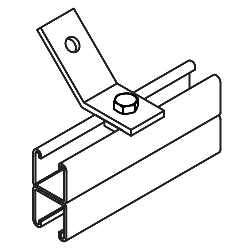
Brace Bolted to Channel
3" Min. End Distance
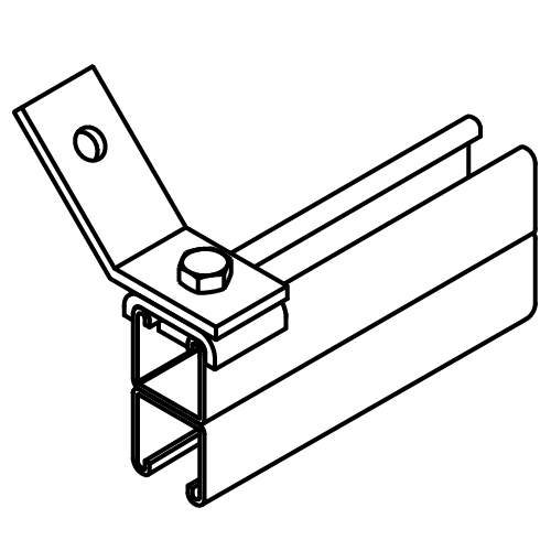
Brace Bolted to Channel
Flush to End
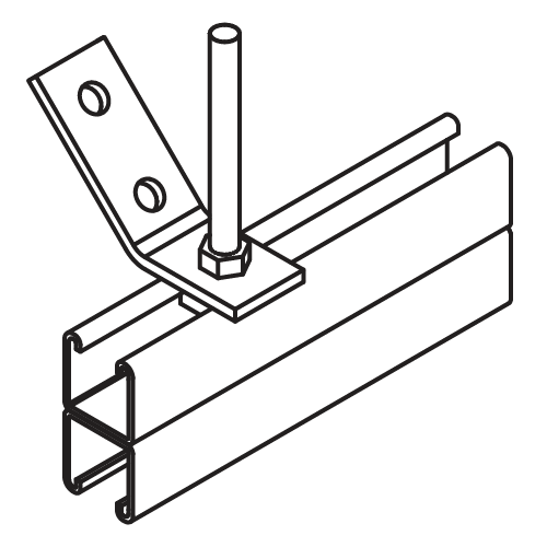
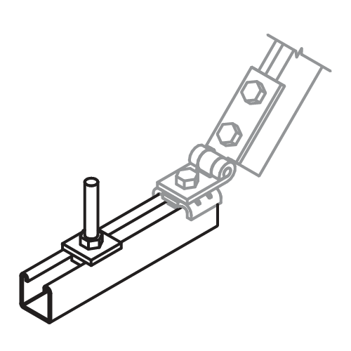
Brace Around Rod to Channel
3" Min. End Distance
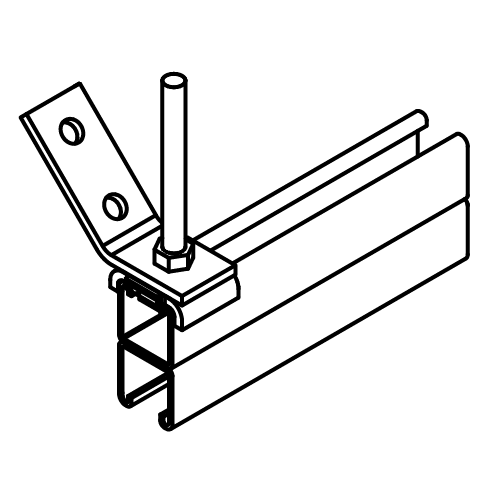
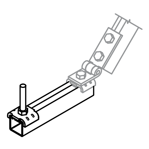
Brace Around Rod to Channel
Flush to End
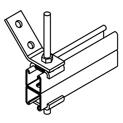
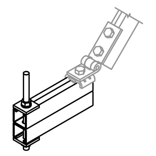
Brace Around Rod Thru Channel
1-1/2" Min. End Distance
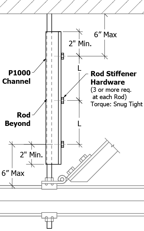
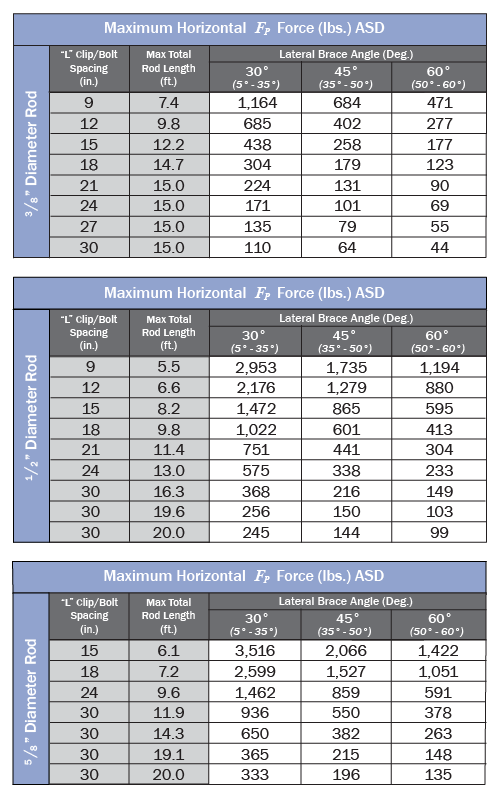
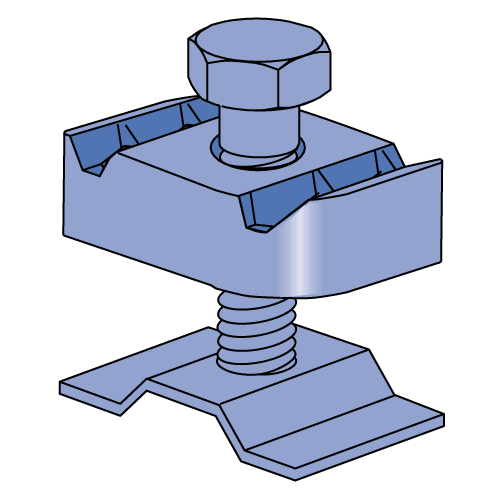
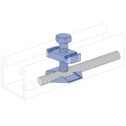
6) Rod Stiffeners
