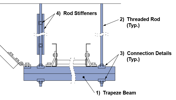
Seismic Trapeze

Seismic - Trapeze Overview 01


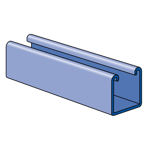
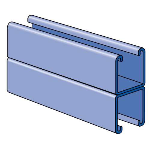
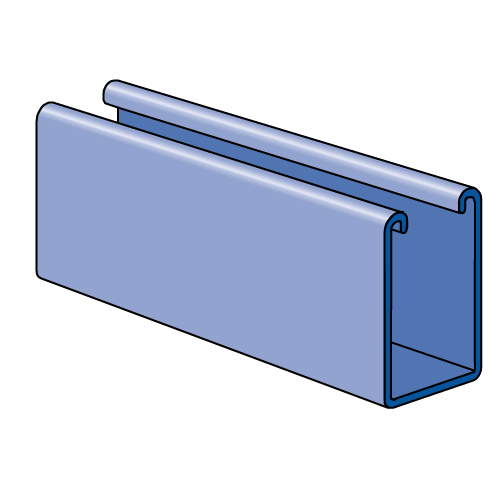
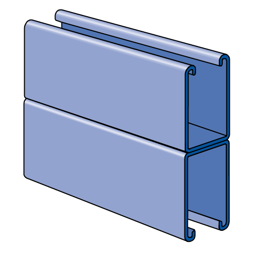
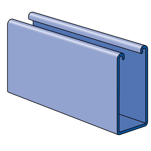
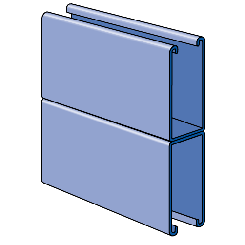
1) Beam Member

Maximum Allowable Uniform Vertical Load (lbs)
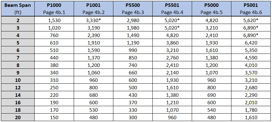
Trapeze Beam OPM Capacities

Notes:

  1. These values apply only to Unistrut brand products. Unistrut channels are stamped with the name "UNISTRUT".
  2. Values in this table are valid with all solid, T, WT and HS pierced channels of the above channel profiles.
  3. * Load is limited by spot weld shear. Weld shear and tension are accounted for in the above listed capacities.
  4. Refer to OPM Page 4b.0 for the detailed calculation procedure.

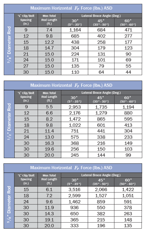
2) Threaded Rod


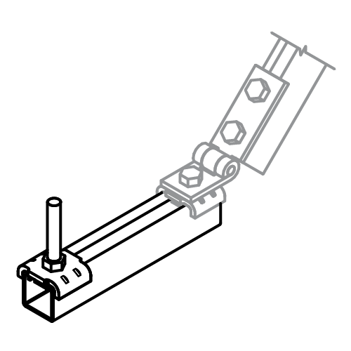
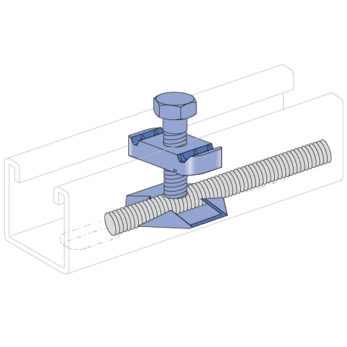
3) Connection Details
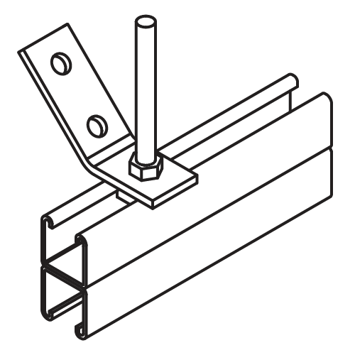
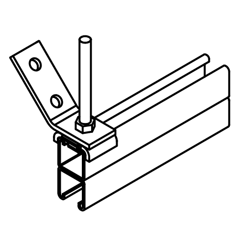
Connection Detail - Brace Around Rod to Channel-01 v2

Brace Around Rod to Channel

(OPM Page 5a.3)

3" Min. End Distance

  • FP Transverse = 1,370 lbs
  • FP Longitudinal = 1,035 lbs (640 lbs opp.)
  • FP Vertical = 2,810 lbs
  •  

    Connection Detail - Brace Around Rod to Channel 2-01

    Brace Around Rod to Channel

    (OPM Page 5a.4)

    Flush to End

  • FP Transverse = 2,375 lbs
  • FP Longitudinal = 935 lbs (640 lbs opp.)
  • FP Vertical = 2,605 lbs
  •  

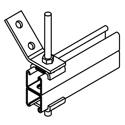
    Connection Detail - Brace Around Rod thru Channel-01

    Brace Around Rod Thru Channel

    (OPM Page 5a.5)

    1-1/2" Min. End Distance

  • FP Transverse = 1,565 lbs
  • FP Longitudinal = 935 lbs (640 lbs opp.)
  • FP Vertical = 2,068 lbs
  •  

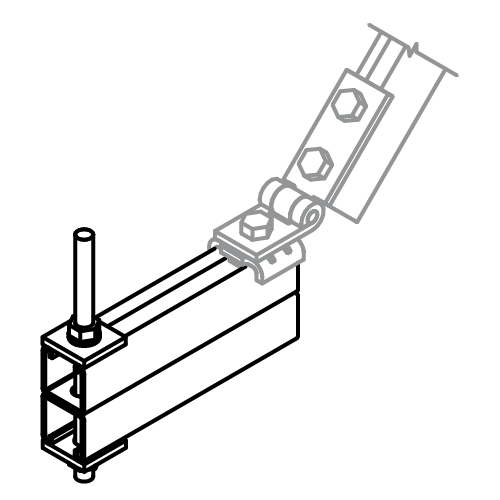
    Connection Detail - Rod thru Channel-01

    Rod Thru Channel

    (OPM Page 5a.6)

    Flush to End

    • FP Vertical = 2,068 lbs
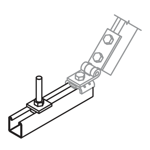
    Connection Detail - Rod to Channel Standard-01

    Rod to Channel

    (OPM Page 5a.7)

    3" Min. End Distance

    • FP Vertical = 2,065 lbs
    Connection Detail - Rod to Channel w Wolf Washer-01

    Rod to Channel

    (OPM Page 5a.7)

    Flush to End

    • FP Vertical = 2,065 lbs

    Connection Components

    4) Rod Stiffeners
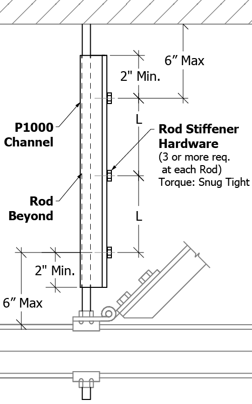
    Rod Stiffener Detail-01
    Rod Stiffener Charts-01