P3354 thru P3370 - Concrete Inserts (16 in - 20 ft)


12 Gauge Concrete Insert (Channel Style)
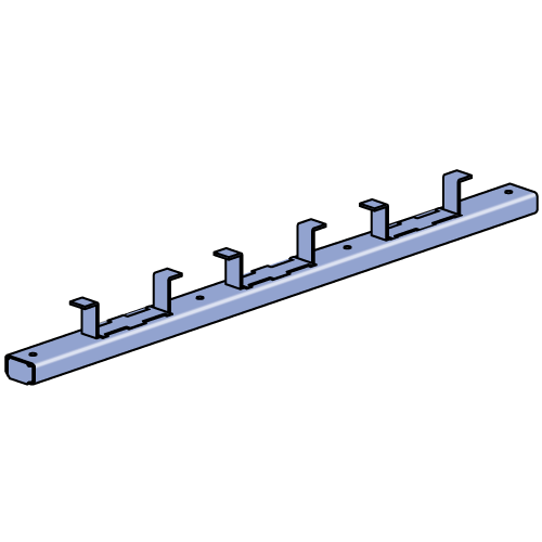
Unistrut's P3300 Series Concrete Insert is ideal for anchoring structures and supports to concrete. This product allows easy installation before the concrete is poured, and attachment anywhere along its length using 1-5/8" Fittings, Channel Nuts or other products. It is perfect for applications that may need to be re-configured or re-anchored.
This product may be used for anchorage on ceilings, floors or walls. Being a pre-pour installation, it is ideal for applications with cracked concrete concerns and avoids the creation of Silica Dust during installation (see OSHA 29 CFR §1926.1153 and 29 CFR §1910.1053).
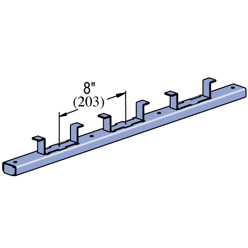
Channel dimensions are 1 5/8" wide x 7/8" deep x 12 ga. thick. Embedment tabs are spaced at 8" O.C. and have an embedment depth of 2-3/8". The product may be supplied with Back Plates, End Caps and a Closure Strip to prevent concrete seepage into the channel, per the options below.
Our P3300 Series is available in Pre-Galvanized (PG), Hot-Dip Galvanized (HG), Plain (PL), and Stainless Steel (SS or ST).
Options:
- "NC" Suffix - No Closure Strip, with End Caps & Back Plates
- "WC" Suffix - With Closure Strip, End Caps & Back Plates
- "X" Suffix - No Closure Strip, no End Caps, with Back Plates
| Part No. | Length (ft) | Finish | Product Weight / Piece (lbs) |
|---|---|---|---|
| P3354NC | 16" (406) | PG | 1.85 |
| P3354NC | 16" (406) | PL | 1.85 |
| P3354WC | 16" (406) | PG | 1.85 |
| P3354WC | 16" (406) | PL | 1.85 |
| P3355NC | 20" (508) | PG | 2.31 |
| P3355NC | 20" (508) | PL | 2.31 |
| P3355WC | 20" (508) | PG | 2.31 |
| P3355WC | 20" (508) | PL | 2.31 |
| P3356NC | 24" (610) | PG | 2.77 |
| P3356NC | 24" (610) | PL | 2.77 |
| P3356WC | 24" (610) | PG | 2.77 |
| P3356WC | 24" (610) | PL | 2.77 |
| P3357ANC | 36" (914) | PG | 4.16 |
| P3357ANC | 36" (914) | PL | 4.16 |
| P3357AWC | 36" (914) | PG | 4.16 |
| P3357AWC | 36" (914) | PL | 4.16 |
| P3357NC | 32" (813) | PG | 3.7 |
| P3357NC | 32" (813) | PL | 3.7 |
| P3357NC | 32" (813) | SS | 3.83 |
| P3357WC | 32" (813) | PG | 3.7 |
| P3357WC | 32" (813) | PL | 3.7 |
| P3358NC | 40" (1,016) | PG | 4.63 |
| P3358NC | 40" (1,016) | PL | 4.63 |
| P3358WC | 40" (1,016) | PG | 4.63 |
| P3358WC | 40" (1,016) | PL | 4.63 |
| P3359NC | 4 Ft. (1,219) | PG | 5.55 |
| P3359NC | 4 Ft. (1,219) | PL | 5.55 |
| P3359WC | 4 Ft. (1,219) | PG | 5.55 |
| P3359WC | 4 Ft. (1,219) | PL | 5.55 |
| P3360NC | 5 Ft. (1,524) | PG | 6.94 |
| P3360NC | 5 Ft. (1,524) | PL | 6.94 |
| P3360WC | 5 Ft. (1,524) | PG | 6.94 |
| P3360WC | 5 Ft. (1,524) | PL | 6.94 |
| P3360X | 5 Ft. (1,524) | SS | 5.57 |
| P3361NC | 6 Ft. (1,829) | PG | 8.32 |
| P3361NC | 6 Ft. (1,829) | PL | 8.32 |
| P3361WC | 6 Ft. (1,829) | PG | 8.32 |
| P3361WC | 6 Ft. (1,829) | PL | 8.32 |
| P3361X | 6 Ft. (1,829) | PG | 8.79 |
| P3361X | 6 Ft. (1,829) | SS | 8.79 |
| P3362NC | 7 Ft. (2,134) | PG | 9.71 |
| P3362NC | 7 Ft. (2,134) | PL | 9.71 |
| P3362WC | 7 Ft. (2,134) | PG | 9.71 |
| P3362WC | 7 Ft. (2,134) | PL | 9.71 |
| P3363NC | 8 Ft. (2,438) | PG | 11.1 |
| P3363NC | 8 Ft. (2,438) | PL | 11.1 |
| P3363WC | 8 Ft. (2,438) | PG | 11.1 |
| P3363WC | 8 Ft. (2,438) | PL | 11.1 |
| P3363X | 8 Ft. (2,438) | PG | 11.59 |
| P3364NC | 9 Ft. (2,743) | PG | 12.49 |
| P3364NC | 9 Ft. (2,743) | PL | 12.49 |
| P3364WC | 9 Ft. (2,743) | PG | 12.49 |
| P3364WC | 9 Ft. (2,743) | PL | 12.49 |
| P3365NC | 10 Ft. (3,048) | PG | 13.87 |
| P3365NC | 10 Ft. (3,048) | PL | 13.87 |
| P3365WC | 10 Ft. (3,048) | PG | 13.87 |
| P3365WC | 10 Ft. (3,048) | PL | 13.87 |
| P3365WC | 10 Ft. (3,048) | SS | 14.8 |
| P3366NC | 12 Ft. (3,658) | PG | 16.65 |
| P3366NC | 12 Ft. (3,658) | PL | 16.65 |
| P3366WC | 12 Ft. (3,658) | PG | 16.65 |
| P3366WC | 12 Ft. (3,658) | PL | 16.65 |
| P3366X | 12 Ft. (3,658) | PG | 17.92 |
| P3367NC | 14 Ft. (4,267) | PG | 19.42 |
| P3367NC | 14 Ft. (4,267) | PL | 19.42 |
| P3367WC | 14 Ft. (4,267) | PG | 19.42 |
| P3367WC | 14 Ft. (4,267) | PL | 19.42 |
| P3368NC | 16 Ft. (4,877) | PG | 22.2 |
| P3368NC | 16 Ft. (4,877) | PL | 22.2 |
| P3368WC | 16 Ft. (4,877) | PG | 22.2 |
| P3368WC | 16 Ft. (4,877) | PL | 22.2 |
| P3368X | 16 Ft. (4,877) | PG | 23.36 |
| P3369NC | 18 Ft. (5,486) | PG | 24.97 |
| P3369X | 18 Ft. (5,486) | SS | 26.14 |
| P3370NC | 20 Ft. (6,096) | PG | 27.75 |
| P3370NC | 20 Ft. (6,096) | PL | 27.75 |
| P3370W | 20 Ft. (6,096) | SS | 27 |
| P3370WC | 20 Ft. (6,096) | PG | 27.75 |
| P3370WC | 20 Ft. (6,096) | PL | 27.75 |
| P3370X | 20 Ft. (6,096) | PG | 29.6 |
| P3370X | 20 Ft. (6,096) | HG | 31.38 |
| P3370X | 20 Ft. (6,096) | PL | 29.6 |
| P3370X | 20 Ft. (6,096) | SS | 29.8 |
| P3370X | 20 Ft. (6,096) | ST | 29.8 |
Design Loads
| Part Number | Insert Length in or ft (mm) |
Max. Allowable Point Load lbs (kN) |
Min. Spacing of Point Loads in (mm) |
Max. Allowable Uniform Load lbs (kN) |
Max. Allowable Uniform Load lbs/ft (kg/m) |
| P3354 | 16" (406.4) | 1,500 (6.67) |
12" (304.8) | 3,000 (13.34) | - |
| P3355 | 20" (508.0) | 1,500 (6.67) |
12" (304.8) |
3,000 (13.34) |
- |
| P3356 | 24" (609.6) | 1,500 (6.67) |
12" (304.8) |
3,000 (13.34) |
- |
| P3357 | 32" (812.8) | 1,500 (6.67) |
12" (304.8) |
- | 1,500 (2,232.2) |
| P3357A | 36" (914.4) | 1,500 (6.67) |
12" (304.8) |
- | 1,500 (2,232.2) |
| P3358 | 40" (1,016.0) | 1,500 (6.67) |
12" (304.8) |
- | 1,500 (2,232.2) |
| P3359 | 4' (1,219.2) | 1,500 (6.67) |
12" (304.8) |
- | 1,500 (2,232.2) |
| P3360 | 5' (1,524.0) | 1,500 (6.67) |
12" (304.8) |
- | 1,500 (2,232.2) |
| P3361 | 6' (1,828.8) | 1,500 (6.67) |
12" (304.8) |
- | 1,500 (2,232.2) |
| P3362 | 7' (2,133.6) | 1,500 (6.67) |
12" (304.8) |
- | 1,500 (2,232.2) |
| P3363 | 8' (2,438.4) | 1,500 (6.67) |
12" (304.8) |
- | 1,500 (2,232.2) |
| P3364 | 9' (2,743.2) | 1,500 (6.67) |
12" (304.8) |
- | 1,500 (2,232.2) |
| P3365 | 10' (3,048.0) | 1,500 (6.67) |
12" (304.8) |
- | 1,500 (2,232.2) |
| P3366 | 12' (3,657.6) | 1,500 (6.67) |
12" (304.8) |
- | 1,500 (2,232.2) |
| P3367 | 14' (4,267.2) | 1,500 (6.67) |
12" (304.8) |
- | 1,500 (2,232.2) |
| P3368 | 16' (4,876.8) | 1,500 (6.67) |
12" (304.8) |
- | 1,500 (2,232.2) |
| P3369 | 18' (5,486.4) | 1,500 (6.67) |
12" (304.8) |
- | 1,500 (2,232.2) |
| P3370 | 20' (6,096.0) | 1,500 (6.67) |
12" (304.8) |
- | 1,500 (2,232.2) |
- Design loads are based on 3,000 PSI concrete, unless noted otherwise.
- Safety Factor = 3.0
Load Criteria


General Specifications
Specifications:
- Includes closure and end caps unless otherwise requested.
- P3380 end cap used with distance to first anchor is up to 2" (51 mm).
- P3703 end cap is used when end distance to first anchor is over 2" (51 mm).
- Nail or anchor inserts to forms every 16" (406.4 mm) to 24" (609.6 mm).
- Anchors are 8" (203.3 mm) on center.
Options:
- "NC" Suffix - No Closure Strip, with End Caps & Back Plates
- "WC" Suffix - With Closure Strip, End Caps & Back Plates
- "X" Suffix - No Closure Strip, no End Caps, with Back Plates
Materials & Finishes
Materials & Finishes - Standard:
- Pregalvanized (PG): Conforms to ASTM A653 SS GR 33, G90.
- Unistrut Defender (DF): Conforms to ASTM A1046 SS GR 33
- Hot Dip Galvanized (HG): Steel conforms to ASTM A1011 SS GR 33, Finish conforms to ASTM A123
- Perma-Green (GR): Steel conforms to ASTM A1011 SS GR 33, E-Coat finish
- Perma-Gold (ZD): Steel conforms to ASTM A1011 SS GR 33, Finish conforms to ASTM B633, Type II SC3
- Plain (PL): Conforms to ASTM A1011 SS GR 33
- Stainless Steel, Type 304 (SS): ASTM A240, Type 304 *
- Stainless Steel, Type 316 (ST): ASTM A240, Type 316 *
- Aluminum (EA): ASTM B221, Type 6063-T6 (Extruded) *
* These materials have different physical properties and performance characteristics. Please contact us for design support.