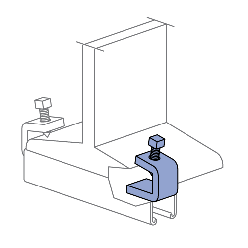
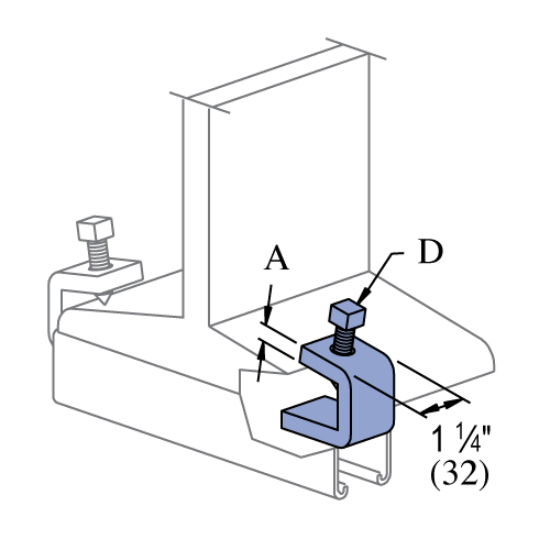
P1272S, P1985S & P1986S - Beam Clamp (1-5/8" Series)
| Part No. | Nom. Pipe Size | A | D | Finish | Flange Thickness | Product Weight / Piece (lbs) |
|---|---|---|---|---|---|---|
| P1272S | Up to 3/4" | 1/4" (6) | 3/8"-16 x 1-1/2" | EG | Up to 3/4" (Up to 19mm) | 0.39 |
| P1272S | Up to 3/4" | 1/4" (6) | 3/8"-16 x 1-1/2" | HG | Up to 3/4" (Up to 19mm) | 0.413 |
| P1272S | Up to 3/4" | 1/4" (6) | 3/8"-16 x 1-1/2" | GR | Up to 3/4" (Up to 19mm) | 0.39 |
| P1985S | Up to 3/4" | 3/8" (10) | 1/2"-13 x 1-1/2" | EG | Up to 3/4" (Up to 19mm) | 0.62 |
| P1985S | Up to 3/4" | 3/8" (10) | 1/2"-13 x 1-1/2" | HG | Up to 3/4" (Up to 19mm) | 0.657 |
| P1985S | Up to 3/4" | 3/8" (10) | 1/2"-13 x 1-1/2" | GR | Up to 3/4" (Up to 19mm) | 0.62 |
| P1986S | 7/8" to 2" | 3/8" (10) | 1/2"-13 x 1-1/2" | EG | 7/8" to 2" (22mm - 51mm) | 0.83 |
| P1986S | 7/8" to 2" | 3/8" (10) | 1/2"-13 x 1-1/2" | HG | 7/8" to 2" (22mm - 51mm) | 0.88 |
| P1986S | 7/8" to 2" | 3/8" (10) | 1/2"-13 x 1-1/2" | GR | 7/8" to 2" (22mm - 51mm) | 0.83 |
Design Loads & Installation
| Design Loads - P1272S, P1985S & P1986S | ||
|---|---|---|
| Part Number | "A" in (mm) |
Design Load Per Pair (Use in Pairs Only) lbs (kN) |
| P1272S | 1/4" (6.4) | 450 (2.00) |
| P1985S | 3/8" (9.5) | 1,000 (4.45) |
| P1986S | 3/8" (9.5) | 900 (4.00) |
Notes:
- Design loads only apply to Unistrut brand products. Look for "UNISTRUT" on the part.
- Use in pairs only.
- Safety factor = 2.5 based on ultimate strength of connection.
- Set Screw "D" is supplied with this part.
- Set Screw Installation Torque:
P1272S: 60 in-lbs (7 N-m)
P1985S & P1986S: 125 in-lbs (14 N-m)
Seismic Design Loads
| P1985S Allowable (Design) Loads (lbs) |
||
| Pullout | Slip Along | Slip Thru |
| 1,000 | 900 | 500 |
Notes:
- Design loads only apply to Unistrut brand products. Look for "UNISTRUT" on the part.
- Seismic design loads are for the P1985S part only and for the 2 clamp installation as shown above.
- Must use clamps in pairs as shown above.
- Design loads are based on static testing with a safety factor = 5 based on ultimate strength of connection.
- Set Screw Installation Torque: 125 in-lbs (14 N-m)
General Specifications
Standard Dimensions (Unless Shown Otherwise on Drawing):
- Hole Diameter: 9/16" (14mm)
- Hole Spacing (From End): 13/16" (21mm)
- Hole Spacing (On-Center): 1 7/8" (48mm)
- Width: 1 5/8" (41mm)
- Thickness:
- 1/4" (6.4mm) with steel meeting or exceeding ASTM A1011 SS GR 33, or
- 0.220" (5.6mm) with steel meeting or exceeding ASTM A1011 HSLAS GR 45
Note:
- When used for mechanical supports, load capacities of brackets and fittings should be in compliance with the American Standard Code for Pressure Piping.
Materials & Finishes
Materials & Finishes - Standard:
- Base Metal: Steel conforms to ASTM A1011 SS GR 33, A1011 HSLAS GR 45, A36, A575, A576, or A635.
- Electrogalvanized (EG): Conforms to ASTM B633, Type III SC1
- Unistrut Defender (DF): Conforms to ASTM A1059
- Hot Dip Galvanized (HG): Conforms to ASTM A123 or A153
- Perma-Green (GR): Conforms to commercial standards for powder coating
- Perma-Gold (ZD): Conforms to ASTM B633, Type II SC1 or SC3
- Plain (PL): No finish
Materials & Finishes - Special Metals:
- Stainless Steel, Type 304 (SS): Conforms to ASTM A240 or A276, Type 304 *
- Stainless Steel, Type 316 (ST): Conforms to ASTM A240 or A276, Type 316 *
- Aluminum (AL): Conforms to ASTM B209, Type 1100F or 5052-H32 *
* These materials have different physical properties and performance characteristics. Please contact us for design support.


