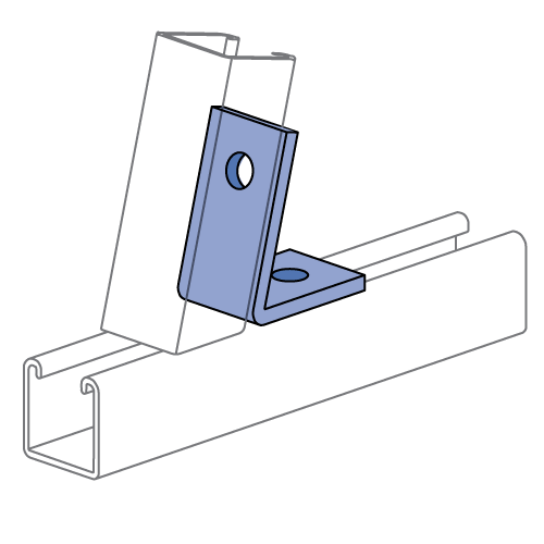
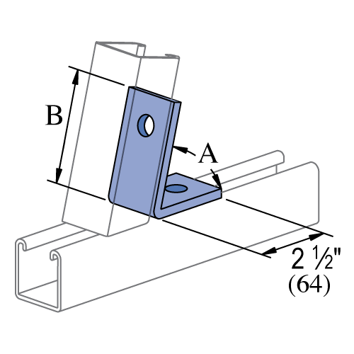
P1186, P2105 thru P2110 - Inside Angle Fitting (1-5/8" Series)
| Part No. | A | B | Finish | Product Weight / Piece (lbs) |
|---|---|---|---|---|
| P1186 | 45° | 3-1/8" (79) | EG | 0.58 |
| P1186 | 45° | 3-1/8" (79) | DF | 0.615 |
| P1186 | 45° | 3-1/8" (79) | HG | 0.615 |
| P1186 | 45° | 3-1/8" (79) | GR | 0.58 |
| P1186 | 45° | 3-1/8" (79) | ZD | 0.58 |
| P1186 | 45° | 3-1/8" (79) | SS | 0.58 |
| P2105 | 82-1/2° | 3-3/16" (81) | EG | 0.58 |
| P2105 | 82-1/2° | 3-3/16" (81) | HG | 0.615 |
| P2105 | 82-1/2° | 3-3/16" (81) | GR | 0.58 |
| P2105 | 82-1/2° | 3-3/16" (81) | ZD | 0.58 |
| P2106 | 75° | 3-3/16" (81) | EG | 0.58 |
| P2106 | 75° | 3-3/16" (81) | HG | 0.615 |
| P2106 | 75° | 3-3/16" (81) | GR | 0.58 |
| P2106 | 75° | 3-3/16" (81) | ZD | 0.58 |
| P2107 | 67-1/2° | 3-1/8" (79) | EG | 0.58 |
| P2107 | 67-1/2° | 3-1/8" (79) | HG | 0.615 |
| P2107 | 67-1/2° | 3-1/8" (79) | GR | 0.58 |
| P2107 | 67-1/2° | 3-1/8" (79) | PL | 0.58 |
| P2107 | 67-1/2° | 3-1/8" (79) | ZD | 0.58 |
| P2108 | 60° | 3-1/8" (79) | EG | 0.58 |
| P2108 | 60° | 3-1/8" (79) | HG | 0.615 |
| P2108 | 60° | 3-1/8" (79) | GR | 0.58 |
| P2108 | 60° | 3-1/8" (79) | ZD | 0.58 |
| P2108 | 60° | 3-1/8" (79) | SS | 0.58 |
| P2109 | 52-1/2° | 3-1/16" (78) | EG | 0.58 |
| P2109 | 52-1/2° | 3-1/16" (78) | HG | 0.615 |
| P2109 | 52-1/2° | 3-1/16" (78) | GR | 0.58 |
| P2109 | 52-1/2° | 3-1/16" (78) | ZD | 0.58 |
| P2110 | 37-1/2° | 3" (76) | EG | 0.58 |
| P2110 | 37-1/2° | 3" (76) | HG | 0.615 |
| P2110 | 37-1/2° | 3" (76) | GR | 0.58 |
| P2110 | 37-1/2° | 3" (76) | ZD | 0.58 |
| P2110 | 37-1/2° | 3" (76) | SS | 0.58 |
Angular Design Loads
| Design Loads - P1186, P2105 thru P2110 | ||||
|---|---|---|---|---|
| Part Number | Angle | Average Ultimate Tension (lbs) |
Design Tension Load (lbs) |
Average Deflection at Design Tension Load |
| P2105 | 82-1/2° | 5,800 | 1,500 | 0.140" |
| P2106 | 75° | 6,000 | 1,500 | 0.147" |
| P2107 | 67-1/2° | 6,000 | 1,500 | 0.179" |
| P2108 | 60° | 5,300 | 1,500 | 0.189" |
| P2109 | 52-1/2° | 5,100 | 1,500 | 0.200" |
| P1186 | 45° | 4,300 | 1,400 | 0.190" |
| P2110 |
37-1/2° | 3,300 | 1,100 | 0.158" |
Notes:
- Design loads only apply to UNISTRUT brand products. Look for "UNISTRUT" on the part.
- Design loads are based on static testing with a Safety Factor = 3.5, except for **, based on ultimate strength of connection. **Safety Factor - 3.0.
- 1/2" Unistrut Channel Nut and Cap Screw torqued to 50 ft-lbs required for installation.
- Design loads limited to 1,500 lbs for Slip Load of Channel Nuts.
- Deflection measured in direction of tension load.
General Specifications
Standard Dimensions (Unless Shown Otherwise on Drawing):
- Hole Diameter: 9/16" (14mm)
- Hole Spacing (From End): 13/16" (21mm)
- Hole Spacing (On-Center): 1 7/8" (48mm)
- Width: 1 5/8" (41mm)
- Thickness:
- 1/4" (6.4mm) with steel meeting or exceeding ASTM A1011 SS GR 33, or
- 0.220" (5.6mm) with steel meeting or exceeding ASTM A1011 HSLAS GR 45
Note:
- When used for mechanical supports, load capacities of brackets and fittings should be in compliance with the American Standard Code for Pressure Piping.
Materials & Finishes
Materials & Finishes - Standard:
- Base Metal: Steel conforms to ASTM A1011 SS GR 33, A1011 HSLAS GR 45, A36, A575, A576, or A635.
- Electrogalvanized (EG): Conforms to ASTM B633, Type III SC1
- Unistrut Defender (DF): Conforms to ASTM A1059
- Hot Dip Galvanized (HG): Conforms to ASTM A123 or A153
- Perma-Green (GR): Conforms to commercial standards for powder coating
- Perma-Gold (ZD): Conforms to ASTM B633, Type II SC1 or SC3
- Plain (PL): No finish
Materials & Finishes - Special Metals:
- Stainless Steel, Type 304 (SS): Conforms to ASTM A240 or A276, Type 304 *
- Stainless Steel, Type 316 (ST): Conforms to ASTM A240 or A276, Type 316 *
- Aluminum (AL): Conforms to ASTM B209, Type 1100F or 5052-H32 *
* These materials have different physical properties and performance characteristics. Please contact us for design support.


