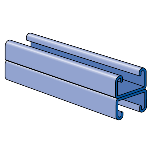
A3301 - 1-1/4" x 1-1/2", 14 Gage Channel
| Part No. | Length (ft) | Finish | Product Weight / Ft (lbs/ft) |
|---|---|---|---|
| A3301 | 10 | PG | 1.56 |
| A3301 | 20 | PG | 1.56 |
| A3301 | 20 | GR | 1.56 |
| A3301 | 10 | GR | 1.56 |
| A3301 | 10 | PL | 1.56 |
| A3301 | 20 | PL | 1.56 |
Beam Loading
| Beam Loading - A3301 | ||||||
|---|---|---|---|---|---|---|
|
Span
(in) |
Max
Allow. Uniform Load
(lbs) |
Deflection at Uniform Load
(in) |
Uniform Loading at Deflection | Lateral Bracing Reduction Factor | ||
|
Span/180
(lbs) |
Span/240
(lbs) |
Span/360
(lbs) |
||||
| 18 | * 990 | 0.03 | * 990 | * 990 | * 990 | 1.00 |
| 24 | 860 | 0.07 | 860 | 860 | 850 | 1.00 |
| 36 | 580 | 0.15 | 580 | 560 | 380 | 1.00 |
| 48 | 430 | 0.27 | 420 | 320 | 210 | 0.99 |
| 60 | 350 | 0.43 | 270 | 200 | 140 | 0.95 |
| 72 | 290 | 0.62 | 190 | 140 | 90 | 0.91 |
| 84 | 250 | 0.85 | 140 | 100 | 70 | 0.88 |
| 96 | 220 | 1.11 | 110 | 80 | 50 | 0.84 |
| Note | *Load limited by weld shear | |||||
Column Loading
| Column Loading - A3301 | |||||
|---|---|---|---|---|---|
|
Unbraced
Height (in) |
Allowable
Load at Slot Face (lbs) |
Max Column Load Applied at C.G. | |||
| K=0.65 (lbs) | K=0.80 (lbs) | K=1.0 (lbs) | K=1.2 (lbs) | ||
| 18 | 2,540 | 9,890 | 9,620 | 9,300 | 9,020 |
| 24 | 2,510 | 9,510 | 9,200 | 8,710 | 7,960 |
| 36 | 2,410 | 8,800 | 7,960 | 6,730 | 5,490 |
| 48 | 2,230 | 7,560 | 6,320 | 4,690 | 3,310 |
| 60 | 1,970 | 6,210 | 4,690 | 3,050 | 2,120 |
| 72 | 1,650 | 4,890 | 3,310 | 2,120 | KL/r>200 |
| 84 | 1,380 | 3,680 | 2,430 | KL/r>200 | KL/r>200 |
| 96 | 1,160 | 2,820 | 1,860 | KL/r>200 | KL/r>200 |
Elements of Section
| Elements of Section - A3301 | ||
|---|---|---|
| Area of Section | 0.459 in2 (3 cm2) | |
| Axis 1-1 | Axix 2-2 | |
| Moment of Inertia (I) | 0.077 in4 (3.2 cm4) | 0.104 in4 (4.3 cm4) |
| Section Modulus (S) | 0.103 in3 (1.7 cm3) | 0.167 in3 (2.7 cm3) |
| Radius of Gyration (r) | 0.411 in (1 cm) | 0.477 in (1.2 cm) |
General Specifications
Standard Lengths:
- 10 feet: 10' or 10’ 1/8” (3.05m) ± 1/2" (13 mm)
- 20 feet: 20' or 20’ 3/8” (6.11m) ± 1/2" (13 mm)
Load Data:
- All beam and column load data pertains to carbon steel and stainless steel channels.
- Load tables apply only to UNISTRUT brand channel. Look for "UNISTRUT" on the product.
- Load tables and charts are constructed to be in accordance with the SPECIFICATION FOR THE DESIGN OF COLD-FORMED STEEL STRUCTURAL MEMBERS 2007 EDITION published by the AMERICAN IRON AND STEEL INSTITUTE USING ASD METHOD.
- Loads are based on 33 ksi steel cold formed to 42 ksi.
- Safety Factor to Yield Strength is 1.67 for Beam Loads and 1.80 for Column Loads.
- Beam loads are based on a simple beam and are given as a total uniform load (W) in pounds. For proper calculation procedures, refer to our Beam Load Calculation Guide.
- For bearing loads, reference our bearing loads page.
Welds:
- Welded channels are spot welded 2" (51 mm) or 3" (76 mm) on-center.
Materials & Finishes
Materials & Finishes - Standard:
- Pregalvanized (PG): Conforms to ASTM A653 SS GR 33, G90.
- Unistrut Defender (DF): Conforms to ASTM A1046 SS GR 33
- Hot Dip Galvanized (HG): Steel conforms to ASTM A1011 SS GR 33, Finish conforms to ASTM A123
- Perma-Green (GR): Steel conforms to ASTM A1011 SS GR 33, E-Coat finish
- Perma-Gold (ZD): Steel conforms to ASTM A1011 SS GR 33, Finish conforms to ASTM B633, Type II SC3
- Plain (PL): Conforms to ASTM A1011 SS GR 33
- Stainless Steel, Type 304 (SS): ASTM A240, Type 304 *
- Stainless Steel, Type 316 (ST): ASTM A240, Type 316 *
- Aluminum (EA): ASTM B221, Type 6063-T6 (Extruded) *
* These materials have different physical properties and performance characteristics. Please contact us for design support.


